
Understanding complex circuit problems is a crucial skill for anyone pursuing a career in electrical engineering. In this article, we will provide the answers to the complex circuit problems discussed in the episode 905 of our series. These problems are designed to test your understanding of circuits with multiple components and their interactions.
Each problem in this episode presents a unique combination of resistors, capacitors, and inductors, along with various sources of voltage and current. By solving these problems, you will gain a deeper understanding of circuit theory, including Ohm’s Law, Kirchhoff’s Laws, and the principles of series and parallel circuits.
In addition to providing the answers, we will also explain the step-by-step process of solving each problem. This will help you learn the necessary techniques and apply them to similar problems in the future. It is important to approach these problems with a systematic mindset, breaking down the circuit into smaller subcircuits and analyzing their behavior individually before combining the results.
By mastering complex circuit problems, you will be prepared to tackle real-world electrical engineering challenges, such as designing and troubleshooting complex electronic systems. So let’s dive into the answers of the complex circuit problems in episode 905 and enhance your circuit analysis skills!
Understanding complex circuit problems
In electrical engineering, circuit problems can range from simple to complex, depending on the number of components and their connections. The ability to understand and solve complex circuit problems is essential for designing and troubleshooting electrical systems. This article will discuss key concepts and strategies to help you tackle complex circuit problems with confidence.
1. Analysis techniques: To solve complex circuit problems, it is crucial to have a strong foundation in analysis techniques such as Kirchhoff’s laws, Ohm’s law, and nodal analysis. These techniques allow you to analyze the behavior of individual components within a circuit and determine voltages, currents, and power dissipation.
Examples:

- Kirchhoff’s laws: Kirchhoff’s current law (KCL) states that the sum of currents entering a node is equal to the sum of currents leaving the node. Kirchhoff’s voltage law (KVL) states that the sum of voltage drops in a closed loop is equal to the sum of the applied voltages.
- Ohm’s law: Ohm’s law relates the voltage across a resistor to the current flowing through it. It states that the current is directly proportional to the voltage and inversely proportional to the resistance.
- Nodal analysis: Nodal analysis is a technique used to determine the voltages at various nodes in a circuit. It involves applying Kirchhoff’s current law to write equations based on the conservation of current at each node.
2. Simplification: Complex circuits can often be simplified by identifying series and parallel combinations of components. By simplifying the circuit, you can reduce it to a more manageable form and apply the analysis techniques mentioned earlier. Simplification techniques include reducing resistors in series to an equivalent resistance and combining resistors in parallel.
3. Problem-solving approach: When faced with a complex circuit problem, it is important to adopt a systematic problem-solving approach. This involves breaking down the problem into smaller, more manageable parts and solving them one at a time. By approaching the problem step by step, you can avoid getting overwhelmed and ensure accuracy in your calculations.
Overall, understanding complex circuit problems requires a solid understanding of analysis techniques, the ability to simplify circuits, and a systematic problem-solving approach. With practice and perseverance, you can master the art of solving complex circuit problems and become a more confident electrical engineer.
Identifying key components in a circuit
In order to understand the function and operation of a complex circuit, it is important to be able to identify the key components that make up the circuit. These components play pivotal roles in the circuit’s operation and understanding them is essential for troubleshooting and designing circuits.
Resistors: Resistors are one of the most common components found in a circuit. They are used to control and limit the flow of electric current. Resistors are typically identified by their resistance value, measured in ohms (Ω), and are represented by various symbols in circuit diagrams.
Capacitors: Capacitors are components that store and release electrical energy. They consist of two conductive plates separated by an insulating material, which stores charge when a voltage is applied. Capacitors are commonly used for filtering, smoothing, and timing signals in circuits.
Inductors: Inductors are components that store energy in a magnetic field when a current flows through them. They typically consist of a coil of wire wound around a core, and they exhibit properties such as self-inductance and inductance. Inductors are commonly used in circuits for filtering, energy storage, and electronic noise suppression.
Diodes: Diodes are electronic components that allow current to flow in one direction while blocking it in the other. They are utilized in circuits for rectification, voltage regulation, and switching applications. Diodes are often represented by arrow-like symbols in circuit diagrams.
Transistors: Transistors are semiconducting devices that can amplify or switch electronic signals and electrical power. They are fundamental to modern electronics and are used in a wide range of applications, including amplifiers, oscillators, and digital logic circuits.
Integrated Circuits: Integrated circuits (ICs) are miniature electronic circuits that are fabricated onto a single semiconductor chip. They can contain thousands or millions of transistors, resistors, capacitors, and other components, and can perform complex functions. ICs are commonly used in computers, mobile devices, and other electronic systems.
By being able to identify these key components in a circuit, one can gain a better understanding of how the circuit functions and how to troubleshoot any problems that may arise.
Solving circuit problems using Ohm’s law
Solving circuit problems often involves applying Ohm’s law, which relates the voltage, current, and resistance in a circuit. Ohm’s law states that the current flowing through a conductor is directly proportional to the voltage across it and inversely proportional to its resistance.
One way to solve circuit problems using Ohm’s law is to first identify the voltage, current, and resistance values given in the problem. Then, apply the appropriate formula to calculate the missing value.
For example, consider a circuit with a voltage of 12 volts and a resistance of 4 ohms. To find the current flowing through the circuit, we can use the formula I = V/R, where I is the current, V is the voltage, and R is the resistance. Plugging in the given values, we get I = 12/4 = 3 amps.
If the current and resistance are given, we can use Ohm’s law to find the voltage. For instance, if the current is 2 amps and the resistance is 6 ohms, we can use the formula V = I * R. Substituting the given values, we get V = 2 * 6 = 12 volts.
Ohm’s law can also be used to calculate the resistance if the voltage and current are known. To find the resistance, we can use the formula R = V/I. For example, if the voltage is 9 volts and the current is 3 amps, the resistance can be calculated as R = 9/3 = 3 ohms.
In more complex circuit problems, Ohm’s law can be applied to individual components within the circuit, and the results can be combined to find the overall voltage, current, or resistance in the circuit. By using Ohm’s law as a fundamental principle, we can solve various circuit problems and analyze the behavior of electrical systems.
Applying Kirchhoff’s laws to complex circuits

In the field of electrical engineering, Kirchhoff’s laws are fundamental principles that are applied to analyze and solve complex circuit problems. These laws, named after the German physicist Gustav Kirchhoff, provide a systematic approach to understanding the behavior of electrical currents and voltages in a network of connected components.
One of Kirchhoff’s laws, the first law, also known as Kirchhoff’s current law (KCL), states that the sum of currents entering a node or junction in a circuit must equal the sum of currents leaving that node. Essentially, this law ensures that charge is conserved within the circuit. By applying KCL, engineers can solve for unknown currents in complex circuits by setting up equations based on the current relationships at each junction.
For example:
- Consider a circuit with multiple resistors connected in parallel. To find the total current flowing through the circuit, one can apply KCL at the junction where the parallel resistors meet. The sum of currents entering the junction, equal to the total current, must be equal to the sum of currents leaving the junction, which are the individual currents flowing through each resistor.
Kirchhoff’s second law, known as Kirchhoff’s voltage law (KVL), states that the sum of voltage drops around any closed loop in a circuit must equal zero. This law is based on the principle of energy conservation and allows engineers to calculate unknown voltages in complex circuits by setting up loop equations using the voltage relationships across each component.
For example:
- Consider a circuit with multiple batteries and resistors connected in series. By applying KVL to a closed loop around the circuit, one can set up equations that equate the sum of voltage drops across the resistors to the total voltage supplied by the batteries. Solving these equations can help determine the unknown voltages or currents in the circuit.
In conclusion, Kirchhoff’s laws are powerful tools that engineers use to analyze and solve complex circuit problems. By applying these laws, one can effectively determine the behavior of electrical currents and voltages within a circuit, making them essential in electrical engineering.
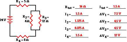
Analyzing Circuit Problems Using Equivalent Resistance
When analyzing complex circuit problems, one useful concept is the concept of equivalent resistance. Equivalent resistance refers to a single resistor that can represent the combined effect of multiple resistors in a circuit. By calculating the equivalent resistance, it becomes easier to analyze the overall behavior of the circuit and solve for various parameters.
To find the equivalent resistance of a series circuit, where resistors are connected in a single line, you simply add up the individual resistances. For example, if you have three resistors with resistances of 5 ohms, 10 ohms, and 15 ohms connected in series, the equivalent resistance would be 30 ohms.
In contrast, finding the equivalent resistance of a parallel circuit, where resistors are connected across each other, requires a slightly different approach. The inverse of the equivalent resistance is equal to the sum of the inverses of the individual resistances. For instance, if you have three resistors with resistances of 5 ohms, 10 ohms, and 15 ohms connected in parallel, the equivalent resistance would be 1/(1/5 + 1/10 + 1/15).
- In summary, analyzing circuit problems using equivalent resistance involves finding a single resistor that represents the effect of multiple resistors in a circuit.
- For series circuits, the equivalent resistance can be found by simply adding up the individual resistances.
- For parallel circuits, the equivalent resistance can be found using the formula 1/(1/R1 + 1/R2 + … + 1/Rn), where R1, R2, … Rn are the individual resistances.
By utilizing the concept of equivalent resistance, circuit analysis becomes more manageable, allowing engineers and technicians to troubleshoot and design complex circuits more effectively.
Using voltage division and current division in circuit analysis

When analyzing complex circuits, it is often necessary to determine the voltage across or the current through certain components. In such cases, voltage division and current division techniques can be extremely useful tools. These techniques allow us to calculate the desired values by considering the relative resistance or impedance of the components in the circuit.
Voltage division is used to determine the voltage across a specific resistor or impedance in a series circuit. It states that the voltage across a resistor is proportional to its resistance compared to the total resistance in the circuit. The formula for voltage division is:
- VR = (Rx / Rtotal) * Vtotal
where VR is the voltage across the resistor, Rx is the resistance of the specific resistor, Rtotal is the total resistance of the circuit, and Vtotal is the total voltage supplied to the circuit. By using this formula, we can easily calculate the voltage across any resistor in a series circuit.
Current division, on the other hand, is used to determine the current through a specific branch in a parallel circuit. It states that the current through a branch is proportional to the conductance of that branch compared to the total conductance in the circuit. The formula for current division is:
- Ix = (Gx / Gtotal) * Itotal
where Ix is the current through the specific branch, Gx is the conductance of the specific branch, Gtotal is the total conductance of the circuit, and Itotal is the total current supplied to the circuit. By using this formula, we can easily calculate the current through any branch in a parallel circuit.
Both voltage division and current division are essential techniques in circuit analysis, as they provide valuable insights into the behavior of complex circuits. By applying these techniques, engineers and technicians can accurately determine the voltage and current values necessary for proper circuit functioning and troubleshooting.