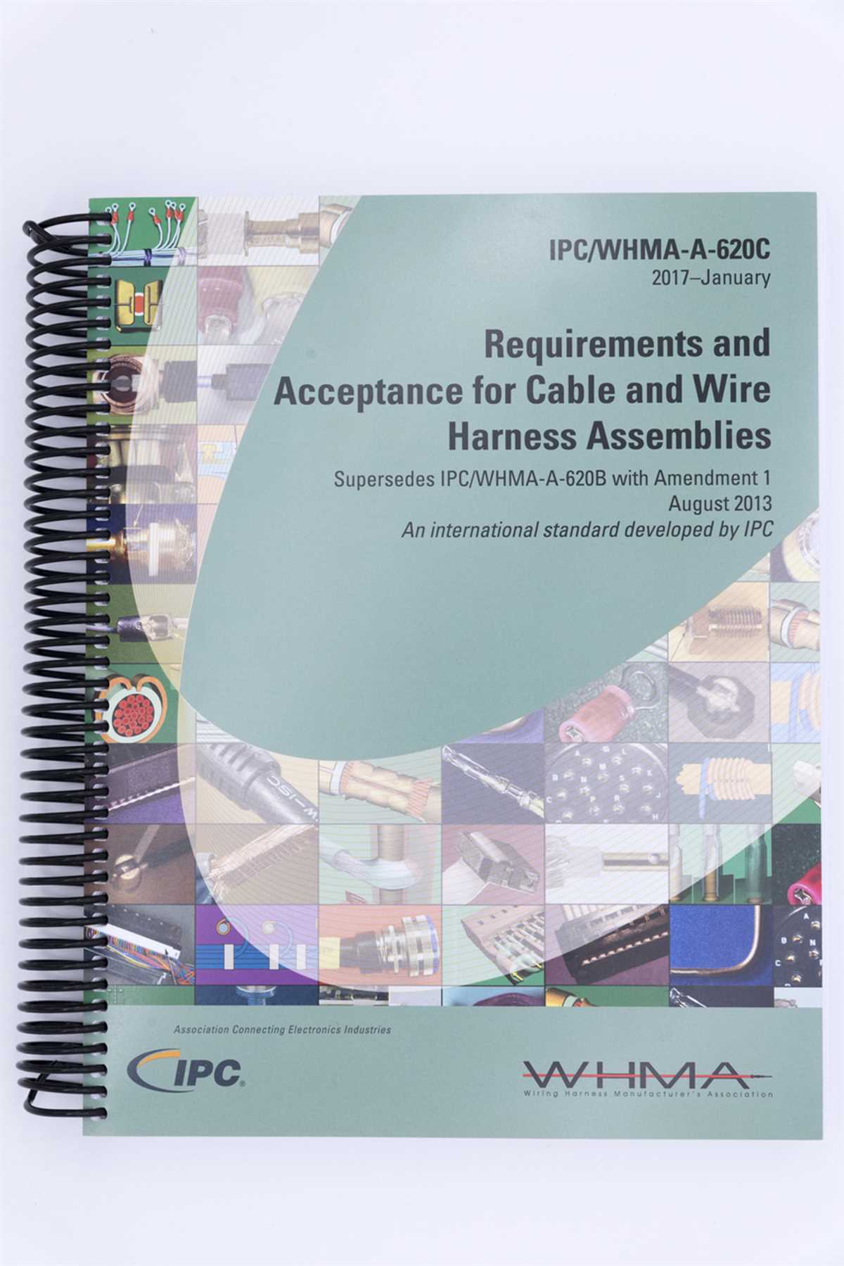
The IPC 620 pull test chart is a valuable resource for anyone working with electrical connections and cable assemblies. This chart provides guidelines and specifications for conducting pull tests on different types of cables, connectors, and terminations. By following the recommendations outlined in the chart, technicians can ensure that their installations meet industry standards and are able to withstand the mechanical stresses commonly encountered in real-world applications.
The IPC 620 standard is developed and maintained by the Association Connecting Electronics Industries (IPC). It outlines the requirements for the design, manufacture, and inspection of cable and wire harness assemblies. The pull test chart is just one component of this comprehensive standard, but it plays a crucial role in ensuring the quality and reliability of cable assemblies.
The pull test chart provides specific guidelines for different types of cables, such as coaxial, ribbon, and individual wires. It also includes recommendations for various connectors and terminations, including crimped, soldered, and insulated terminals. The chart specifies the minimum pull force that each type of cable or termination should be able to withstand without failure, as well as the maximum allowable pull force to prevent damage to the cable or termination.
Ipc 620 Pull Test Chart: What You Need to Know
Pull testing is an essential part of ensuring the quality and reliability of electrical cables and wire harnesses. It helps determine whether the connections can withstand the required forces without coming loose or failing. The IPC 620 pull test chart provides guidelines for conducting these tests and interpreting the results. If you are involved in the manufacturing or inspection of electrical assemblies, understanding the IPC 620 pull test chart is crucial.
The IPC 620 pull test chart outlines the acceptable force levels for different types of connectors and cables. It categorizes connections based on the type of terminal, such as crimps, solder, or insulation displacement. Each category has specific requirements for the minimum pull force that the connection should withstand. By referencing the pull test chart, you can determine the appropriate force for the specific connection you are testing.
The chart also provides guidelines for the testing method. It specifies the rate at which the force should be applied, the duration of the test, and any additional conditions that should be considered. Following these guidelines is important to ensure consistency and accuracy in the test results. The IPC 620 pull test chart also helps in determining whether rework or repair is necessary if a connection fails to meet the minimum pull force requirement.
If you are involved in the manufacturing or inspection of electrical assemblies, familiarizing yourself with the IPC 620 pull test chart is essential. It will help you ensure that the connections in your products meet the necessary standards for quality and reliability. It also provides a common reference point for communication between different stakeholders, such as manufacturers, inspectors, and customers. By following the guidelines outlined in the IPC 620 pull test chart, you can improve the overall quality and performance of your electrical assemblies.
Understanding the Importance of Ipc 620 Pull Test Chart in Electronics Manufacturing
In the field of electronics manufacturing, the IPC 620 Pull Test Chart plays a crucial role in ensuring the quality and reliability of electronic assemblies. This chart provides guidelines and specifications for conducting pull tests on wire and cable connections, helping manufacturers determine if the connections can withstand the required amount of force without failing.
One of the primary reasons why the IPC 620 Pull Test Chart is important is because it helps ensure the safety of electronic devices and systems. Pull tests are conducted to assess the mechanical strength and integrity of wire and cable connections, which are vital components in electronic assemblies. By following the guidelines provided in the pull test chart, manufacturers can avoid potential electrical failures or hazards that could occur due to weak or faulty connections.
The IPC 620 Pull Test Chart also helps manufacturers establish consistent and standardized testing procedures. This is important in ensuring that products meet certain quality standards and specifications. The chart provides clear guidelines on the setup of the pull test apparatus, the required force to be applied, and the acceptance criteria for pass or fail results. By following these standardized procedures, manufacturers can improve the reliability and consistency of their products, reducing the risk of defects or failures.
In addition to safety and standardization, the IPC 620 Pull Test Chart also serves as a reference for quality control and inspection purposes. During the manufacturing process, wire and cable connections are subjected to various stresses, including vibrations, movements, and mechanical loads. By conducting pull tests according to the guidelines in the chart, manufacturers can assess the durability and reliability of these connections, identifying any potential weaknesses or defects that require corrective measures.
In conclusion, the IPC 620 Pull Test Chart is an essential tool in the field of electronics manufacturing. By following its guidelines, manufacturers can ensure the safety, standardization, and quality of their electronic assemblies. Pull tests help assess the mechanical strength and integrity of wire and cable connections, ensuring they can withstand the required forces without failure. Overall, this chart plays a critical role in maintaining the reliability and performance of electronic devices and systems.
Key Factors to Consider When Conducting IPC 620 Pull Tests

When conducting IPC 620 pull tests, there are several key factors that need to be considered in order to ensure accurate and reliable results. These factors include:
1. Test Equipment Calibration:
One of the first and most important factors to consider is the calibration of the test equipment. It is essential to ensure that the equipment being used for the pull test is properly calibrated and functioning correctly. Any errors in calibration can lead to inaccurate test results and potentially jeopardize the integrity of the product being tested.
2. Pull Test Methods:
There are different pull test methods that can be used in IPC 620 testing, including the constant rate of extension (CRE) method and the constant rate of force (CRF) method. It is important to carefully select the appropriate method based on the specific requirements of the project and the type of connection being tested. Each method has its own advantages and limitations, and choosing the right method is crucial to obtaining reliable results.
3. Sample Preparation:
Proper sample preparation is another critical factor in conducting IPC 620 pull tests. The samples being tested should be prepared and installed according to the standards and specifications outlined in the IPC 620 guidelines. This includes ensuring proper connector installation, adequate wire preparation, and proper cable routing. Any deviations from these guidelines can introduce variables that may affect the test results.
4. Pull Test Speed and Load:
The speed at which the pull test is conducted and the load applied during the test also play a significant role in obtaining accurate and reliable results. It is important to adhere to the specified test speeds and loads as outlined in the IPC 620 guidelines. Deviating from these parameters can lead to inconsistent results and may not accurately reflect the performance of the connection being tested.
5. Test Result Documentation:
Finally, it is essential to properly document the test results and any relevant observations or findings. This documentation should include details such as the test equipment used, the sample preparation process, the specific pull test method employed, and the results obtained. This documentation not only provides a record of the test for future reference but also helps in the analysis and interpretation of the test results.
By considering these key factors when conducting IPC 620 pull tests, manufacturers can ensure accurate and reliable results that meet the required standards and specifications. This helps to maintain the integrity and quality of the products being tested, providing assurance to both customers and regulatory bodies.
Common Types of Pull Tests Used in IPC 620 Pull Test Chart
When it comes to testing the strength and integrity of electrical connections, the IPC 620 pull test chart provides a comprehensive guide. This chart outlines various types of pull tests that are commonly used in the industry to ensure the reliability of these connections.
The following are some of the common types of pull tests listed in the IPC 620 pull test chart:
- Wire Pull Test: This test involves pulling a wire or cable in order to measure the force required to break the connection between the wire and its terminal. It assesses the solder joint or other methods of connection used.
- Terminal Pull Test: This test focuses on evaluating the strength of the connection between a terminal and the wire it is crimped onto. It measures the force needed to separate the terminal from the wire.
- Component Pull Test: In this test, a force is applied to a component, such as a resistor or capacitor, to determine its ability to withstand mechanical stress. It assesses the bonding strength between the component and the circuit board.
- SMT Pad Pull Test: This test involves pulling on a surface mount technology (SMT) pad to measure its adhesion strength to the circuit board. It helps verify the quality of soldering and the effectiveness of the bonding material.
- Flex Pull Test: The flex pull test assesses the strength of flexible circuits or cables by subjecting them to repeated bending and pulling. It measures their ability to withstand mechanical stress and maintain electrical continuity.
These pull tests are crucial for determining the reliability and quality of electrical connections in various applications, including aerospace, automotive, and electronics industries. By following the guidelines outlined in the IPC 620 pull test chart, manufacturers can ensure that their products meet the necessary standards and provide safe and reliable performance.
Benefits of Implementing IPC 620 Pull Test Chart in Electronics Manufacturing
The IPC 620 pull test chart is a valuable tool in electronics manufacturing as it provides numerous benefits for ensuring the quality and reliability of assembled electronic components. By following the guidelines outlined in the IPC 620 standard and utilizing the pull test chart, electronics manufacturers can achieve the following advantages:
1. Standardized Testing:
The use of the IPC 620 pull test chart ensures standardized testing procedures across different manufacturing facilities and suppliers. This allows for consistent evaluation of the pull strength of connections, ensuring that the quality remains the same regardless of where the components are manufactured. This standardization greatly enhances the reliability and performance of electronic devices.
2. Reliable Connection Verification:
The pull test chart provides a reliable method for verifying the strength of connections and terminations on electronic assemblies. By applying a controlled and calibrated force to the connection, manufacturers can determine if it meets the required pull strength specifications. This ensures that the connections will not fail during operation or under various environmental conditions, enhancing the overall durability of the product.
3. Quality Control:
Implementing the IPC 620 pull test chart as part of the manufacturing process allows for effective quality control. By regularly conducting pull tests on randomly selected assemblies, manufacturers can identify any potential issues or defects in the assembly process. This proactive approach to quality control helps prevent faulty products from reaching the market, reducing warranty claims and customer dissatisfaction.
4. Compliance with Industry Standards:

Adhering to the IPC 620 pull test chart ensures compliance with industry standards and regulations. This is especially significant in industries where safety and reliability are paramount, such as aerospace, automotive, and medical electronics. By following the guidelines provided by the IPC 620 standard, manufacturers can demonstrate their commitment to meeting the highest industry requirements, fostering trust with customers and regulatory bodies.
5. Process Optimization:
By analyzing the results of pull tests conducted using the IPC 620 pull test chart, manufacturers can identify areas for process optimization. If certain connections consistently fail to meet the required pull strength, adjustments can be made to the assembly process to improve the overall quality and reliability of the product. This continuous improvement approach helps manufacturers stay competitive and increase customer satisfaction.
In conclusion, implementing the IPC 620 pull test chart in electronics manufacturing provides numerous benefits, including standardized testing, reliable connection verification, improved quality control, compliance with industry standards, and process optimization. By utilizing this valuable tool, manufacturers can ensure the quality and reliability of their electronic assemblies, leading to enhanced customer satisfaction and trust.
How to Interpret and Analyze Ipc 620 Pull Test Chart Results
Pull testing is a common method used to evaluate the strength and quality of electrical connectors and cables. The IPC-620 standard provides guidelines and specifications for conducting pull tests on wire and cable assemblies. The results of these tests are typically represented in pull test charts, which can be used to interpret and analyze the performance of the tested assemblies. Understanding how to interpret and analyze IPC-620 pull test chart results is crucial for ensuring the reliability and durability of electrical connections.
1. Understanding the Axis
The pull test chart usually has two axes: the load axis and the elongation axis. The load axis represents the force applied during the test, while the elongation axis represents the amount of elongation or stretch in the tested assembly. By analyzing the relationship between these two axes, it is possible to determine the load at which the assembly fails, as well as its elongation characteristics.
2. Identifying Key Points
When analyzing an IPC-620 pull test chart, it is important to identify key points that provide important insights into the performance of the tested assembly. These key points include the yield point, ultimate load point, and failure point. The yield point represents the maximum load the assembly can withstand without permanent deformation. The ultimate load point represents the maximum load the assembly can withstand before failing. The failure point represents the load at which the assembly fails completely.
3. Comparing Results to Specifications
IPC-620 provides specifications and requirements for various types of wire and cable assemblies. These specifications typically include minimum load and elongation requirements. When analyzing pull test chart results, it is important to compare the obtained values with the specified requirements. If the tested assembly meets or exceeds the specified requirements, it can be considered acceptable. However, if the values fall below the specified requirements, further investigation and analysis may be required to determine the cause of the failure.
4. Consideration of Application Requirements
While IPC-620 provides general specifications for pull testing, it is important to consider the specific requirements of the application. The pull test chart results should be analyzed in the context of the intended use of the assembly. For example, if the assembly is intended for use in a high-stress environment, it may need to meet more stringent requirements than those specified by IPC-620. Therefore, when interpreting pull test chart results, it is crucial to consider the specific application requirements and make informed decisions based on the observed performance.
In conclusion, interpreting and analyzing IPC-620 pull test chart results requires a thorough understanding of the standard’s specifications and requirements, as well as the specific application requirements. By understanding the relationship between the load and elongation axes, identifying key points, comparing results to specifications, and considering application requirements, engineers and technicians can effectively evaluate the performance and reliability of wire and cable assemblies.
Conclusion
Performing successful IPC 620 pull tests in electronics manufacturing is crucial for ensuring the quality and reliability of electrical connections. By following best practices and using the IPC 620 pull test chart as a reference, manufacturers can achieve consistent and accurate test results.
Key takeaway points to remember include:
- Understanding the requirements: Familiarize yourself with the IPC 620 standard and the specific requirements for pull testing in your manufacturing process.
- Proper equipment and setup: Ensure you have the right tools and fixtures in place for conducting pull tests, including calibrated test equipment and appropriate adhesion surfaces.
- Technician training: Train your technicians on proper pull testing techniques and provide clear instructions on how to interpret and record test results.
- Documented procedures: Develop and implement standardized procedures for conducting pull tests, including step-by-step instructions and guidelines for interpreting results.
- Regular equipment maintenance: Keep your pull testing equipment well-maintained and calibrated to ensure accurate measurements.
- Data analysis: Regularly analyze and review pull test data to identify any trends or issues that may indicate process improvements or corrective actions.
By following these best practices, manufacturers can minimize the risk of electrical connection failures, enhance product quality, and meet customer expectations for reliable and durable electronic assemblies.


